In the protection system of electronic equipment, varistors play a vital role, providing protection when the circuit encounters overvoltage conditions. However, just like any other electronic component, a varistor can suffer damage that affects the proper functioning of the entire circuit. This article aims to delve into the detection methods of varistor damage so that problems can be discovered promptly and corresponding repair measures can be taken.
1. Identification of damaged varistor
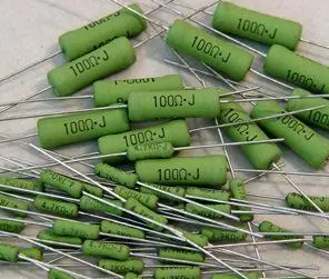
Varistor, as a key voltage-limiting protection component, plays an important role in electronic equipment. Although they are not as susceptible to damage as other components, if something goes wrong, the consequences can be serious. Damage to a varistor usually manifests itself as an open circuit, with occasional increases in resistance, while decreases in resistance are relatively rare. There are many types of resistors, including carbon film resistors, metal film resistors, wirewound resistors, and fuse resistors. Different types of resistors have different appearance characteristics after damage. For example, wire-wound resistors may appear blackened or have surface cracks, while cement resistors may break when burned out. In addition, when the fuse resistor is damaged, its surface may be obviously damaged, but it will not be burned or blackened.

2. Preparation before testing
Before testing the varistor, sufficient preparations must be made. First of all, you need to ensure that the test leads of the multimeter and the pins at both ends of the resistor are correctly connected. There is no need to distinguish between positive and negative in this process. In order to improve the accuracy of measurement, the appropriate range should be selected based on the nominal value of the resistance being measured. This step is crucial for the subsequent testing process, because the correct range selection can ensure the accuracy of the test results.
3. Detailed testing process
The detection process of varistor can be divided into several steps. First, set the multimeter's gear knob to the resistance position and short-circuit the test pen. At this time, you should observe whether the multimeter pointer is pointing to zero. If not, you need to adjust the ohm zero-adjusting potentiometer until the pointer is aligned with zero. Next, select the appropriate magnification block based on the resistance of the resistor being measured. This step is crucial because the reading accuracy of the multimeter is directly affected by the magnification selection. Finally, after each change of the magnification gear, the zero adjustment operation of the resistance gear must be performed again to ensure the accuracy of each measurement.
